
Chapter 3. Input/Output Devices
Since digital images are a representation of the real world, it follows that the real world must somehow be brought into the computer. Similarly, after images have been processed, they must be extracted from the realm of bits and bytes for representation in visual form. These tasks are accomplished by input and output devices, which are a critical link in the chain of digital image processing.
Most sensors, the devices that actually perform the conversion, are nonlinear in nature. This means that if a certain number of photons translates to a specific digital value, doubling the number of photons may not necessarily result in conversion to a value twice as large. That human vision is nonlinear, as will be investigated more throughly in a later chapter, only compounds the problem.
What is seen on the computer display, in respect to color or saturation, may be quite different than the original real-world image that was captured, or the tangible output that is eventually generated.
Various input/output devices available today.
Charge-Coupled Devices (CCD) and Digital Camera
A CCD is a silicon semiconductor that acts like a light detector. An interesting property of crystalline silicon is that the energy from photons causes the bonds between adjacent atoms to be broken, thus leaving electron-hole pairs. The resultant electrical charge is proportional to the amount of light, or number of photons, that strike the silicon. If the silicon chip is subdivided into a very fine grid, as shown below, and an image is focused on that grid, the result is a sensor in which each square holds a charge that is equivalent to the intensity of the light at that point. Each point corresponds to a pixel of the soon-to-be digital image.
This collection of subdivided silicon is referred to as a parallel register, since photons fall on each sensor simultaneously. Once the exposure to light is complete, the data must be retrived from the parallel register. This is accomplished by shifting the collected charges, one row at a time, into another silicon buffer called the serial register. Once a row is captured in the serial register, it is then amplified and transported off the chip one cell, or pixel, at a time. Fig. 3.2 illustrates how this propagation of data works.

The grids on a CCD actually respond only to light - not to colour. Colour is added to the image by means of red, green and blue filters placed over each pixel. As the CCD mimics the human eye, the ration of green filters to that of red and blue is two to one. This is because the human eye is most sensitive to yellow-green light. As a pixel can only represent one colour, the true colour is made by averaging the light intensity of the pixels around it - a process known as color interpolation.

These devices are very susceptible to electromagnetic radiation other than visible light, and are especially sensitive to infrared, or heat, so they are usually cooled to very low temperatures, around -25 to -35 degrees Fahrenheit (-31.7 to -37.2 deg. in Celsius), during operation.
Common sizes of CCD are 512X512, 720X486, 1024X1024, 2048X2048, and even 4096X4096. Figure 3.3 shows how a digital camera is built around this technology. A digital camera looks like a normal 35mm camera but, instead of film, a CCD chip and instead of a canister of unexposed film, a removable disk are used.

CCD technology is also used for scanning photographic film to create digital images. Figure 3.4 shows the principal components of a film scanner. A light source is used to illuminate a film negative. A lens then focuses the images of the film onto a CCD, which converts the light signals to digits, as in the previous description. Filters are placed in front of the light source so that individual exposures of the red, green, and blue film emulsions are captured to produce a color image.

Two major obstacles to generate consistent and accurate results in film scanning.
Unlike taking a picture under natural lighting conditions, a film scanner has an artificial light source that illuminates the film. Unfortunately, no source casts light perfectly evenly over a given area. An uneven illumination field will result in darker or brighter areas in the digital image; this is especially noticeable in areas of even or slowly changing color, such as a blue sky or a painted wall.
flat field correction : a process to eliminate the uneven illumination.
First, an image of the illumination field is captured. A histogram of this
image is generated, as well as the arithematic mean, as shown in Fig. 3.6a.
If the mean value is subtracted from every pixel value in the illumination
field image, the histogram in Fig. 3.6b is the result. Notice that this
image now has positive and negative values. This signed image is the flat
field correction information that will be used to modify scans.

When the film is scanned, the following operation is applied to every pixel:
p = s - (f x s/max)
where, p is the corrected pixel, s is the raw scanned value,
and f is the flat field correction value at that location. Thus a
pixel in a bright area of the illumination field is slightly darkened, while
one in a dim area is brightened. Note that f is scaled by the factor
s/max, where max is the maximum value for a scanned pixel,
which assures that darker pixels are not overcompensated by flat field correction.
Example 1 : Flat Field correction

Linear Arrays and Flatbed Scanners
It uses the same silicon-based semiconductor technology that generates an electrical charge proportional to the amount of light that falls on it. Linear arrays are composed of a single row of sensors instead of the two-dimensional grid used in the chips in digital cameras. Because of this, they are easier and much cheaper to produce.
In order to scan in two-dimensions with one-dimensional linear arrays, scanner move the linear array along a fixed track while the data is continuously retrived from the CCD. A prism-and-lens system is mounted with the chip, so that the projected image of the material being scanned is projected onto the CCD. The light source, which is a fluorescent or halogen tube, is moved along with the lens/CCD assembly. Thus, a two-dimensional image is constructed as a collection of lines.

For creating color digital images, either one or three scanning passes of the material on the platen are performed.

Many of the problems that arise with two-dimensional scanners do not occur with linear array flatbed scanners. Since lighting occurs only along a one-dimensional axis, and since the light source is a tube, achieving a flat field is much easier.
Photomultiplier Tubes (PMT) and Drum Scanners
The drum scanner uses photomultiplier tubes, instead of CCD, as the light sensors. A photomultiplier is a vacuum tube with an opaque cover, except for a small window that permits light to enter. Photons strike the cathode of the tube, which emits electrons. These negatively charged particles, in turn, are attracted to a positively charged dynode that produces a secondary emission of electrons that is greater than the input charge. The number of electrons increases as they cascade through a series of these dynodes, resulting in a signal that entered the device.

Fig. 3.11 shows how photomultipliers are used within a drum scanner. This type of device is designed to scan artwork that is attached to the inside of a plexiglass cylinder, or drum, that spins at speeds of about 600 to 1600 revolutions per minutes. A very bright light source is placed at the axis of the rotating drum and is reflected 90 degrees and focused to illuminate a very small spot on the inside of the drum-where the artwork is attached. The light is attenuated at different frequencies corresponding to the colors of the artwork, and is reflected through a series of filters to separate it into red, green, and blue components. A separate photomultiplier detects the light intensity for each primary color, and from these signals a digital image is created.
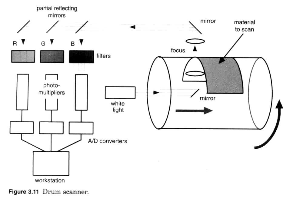
Drum scanners generally are used in the printing industry and are capable of converting both reflective art and transparencies, from 35mm slides to 16-foot × 20 in material at high spatial (10,000 dpi+) resolutions.
Laser Scanners
For scanning film and other transparency material, a laser is used as a light
source.
In an incandescent lamp, an electrical current heats up a coiled
filament inside an evacuated bolb. As it becomes hotter, the filament glows,
giving off both heat and light. A large quantity of heat, or infrared radiation,
is generated compared to a relatively small amount appearing in the form of
visible light. The light that emerges does so in all directions and at many
wavelengths.
A laser (light amplification by stimulated emission of radiation) operates very differently. A glass tube holds a gas whose atoms, when excited by an electrical current, move to a higher quantum energy state. Each atom wants to return to its lower energy state, and does so by emitting a photon. One end of the tube is sealed with a mirror that reflects the light back through the excited gas, while the other end is sealed with a mirror that only partially reflects light. This end allows some of the light to exit the tube, and this is the laser light we see.

Coherency (all of the photons are of the exact same wavelength, or color), intensity(0.5 mW would be about the same as looking directly into the sun), efficiency (laser do not generate much heat), and monochromaticity, make lasers an ideal light source for creating scanners.
A laser is chosen that generates several discrete wavelengths of lights namely red, green, blue. A filter selects the desired wavelength, after which a lens precisely focuses the beam to a very small point. The laser beam must be accurately aimed at every point in the target. This is usually accomplished with a rotating prism and mirror that can move the beam horizontally and vertically.

Scanning Resolution
The determination of the appropriate resolution at which to scan an image is important both in terms of achieving the desired quality and in terms of the efficiency of the scanning process itself. The key point is that scan resolution should always be determined by the capability of the output device. If the scanned image is to be printed at a different size - either larger or smaller than the original - the scan resolution needs to be adjusted accordingly.
As an example, suppose the intention is to print the scan of 1x1.5 inch stamp at a size of 2x3 inch on an inkjet printer that has a print resolution of 600 dpi. If the stamp were to be scanned at a 600 dpi resolution, the scanned image would have 600 pixels vertically and 900 pixels horizontally. Enlarging the image to the intended print size of 2x3 inches reduces the effective resolution to 300 dpi and the same is true in the vertical dimension. For the best quality final printed output - which actually uses the 600 dpi resolution the inkjet is capable of - the image should be scanned at 1200 dpi.
The rules can be summarized by the following formula
SR = (DR x DW ) / OW
where
SR : ideal scanning resolution in dpi
DR : resolution of final display device in dpi
DW : width at which the image will be printed or displayed in inches
OW : width of the original being scanned in inches.
Ink Printers
Printers are the most common form of image output devices. There are dot-matrix printers, inkjet printers, and laser printers.
In Inkjet printers, containers of ink are vibrated by piezoelectric crystals (a thin section of a crystal placed between two electrodes). A difference in voltage cause the crystals to vibrate, setting up precisely timed vibrations causing ink droplets to be sprayed through a nozzle onto the page.

Laser printers use a technology which is similar to that used in copiers.
A laser beam is focused on a photoelectric belt or drum, creating an electrical
charge. This process occurs four times, once for the cyan, magenta, yellow and
black components of the image. Electrostatic charges cause the toners to adhere
to the belt. The image, composed of the four toner colors, is then transferred
to a drum which rolls the toners onto the sheet of paper or transparency, toners
are then heat-fused using heat alone or in combination with pressure.

All Ink printers have one thing in common: They can either deposit or not deposit a dot of ink or toner at a specific spot. For text or simple graphics this works fine, but for images it creates a problem. Most printers cannot be commanded to output three-quarters intensity ink to simulate a pixel that has an 8-bit value of 192, let alone different amounts of ink for the remaining 255 intensity levels.
Solutions are provided by processes known as halftoning and dithering. Both methods make use of a particular phenomenon of human vision, called spatial integration, that causes us to see a group of very small objects as if they were a single large object, with a single intensity that is the average of all the smaller components.
Recall that digital images have both spatial and depth resolution which are closely related and, if it is done properly, one can be traded off for the other. This is how a printer, with only 1-bit depth resolution, can acceptably reproduce an 8-bit image that normally is displayed on a CRT: The spatial resolution is increased to make up for the loss of depth.
Halftoning : producing different patterns of ink dots that correspond to different intensity values of the digital image. Of course, most computer printers cannot generate dots of different sizes, so halftoning is governed by either printing or not printing dots within a localized group. Figure 3.14 illustrates how these groups could be arranged for different-sized dot groups. In general, the number of possible patterns that can be held by a group is given by the formula:
Number of patterns = ( n x n ) - 1
where n is the size of the dot matrix. Therefore, a dot group of 16 will yield 257 patterns, enough to hold all possible pixels values of an 8-bit image. This means that the depth resolution has been reduced to 1 bit, but the spatial resolution has been increased by a factor of 256. (i.e. 1024 x 1024, 8-bit digital image becomes 16384 x 16384 dots ). If the final output size of the print were to be 10 x 10 inches, the resolution would be more than 1600 dpi. Since most printers have maximum resolution of only 300 or 600 dpi, it is unnecessary to obtain anything greater than this. Thus, a 4 x 4 dot group would be sufficient for this example:
10 inches x 300 dpi = 3000 dots
3000 dots /1024 pixels = 2.9 dots per pixel
Therefore, a 4 x 4 dot group that yield 17 patterns will increase the spatial resolution sufficiently.

These choices have been made with some care. The matrices
                                     | 5 3 8 |

  B_2 = | 1 3 |                B_3 = | 9 1 2 |

        | 4 2 |                      | 7 4 6 |
holds the choices for the 2x2 and 3x3 cases. We need to be careful to avoid
some patterns. For example, the leftmost pattern is desirable to represent 2
when compared with the other 3 alternatives.
This is the case because the alternatives will leave stripes in various directions
for a group of adjacent pixels all having intensity 2.
Example : Halftoning
Dithering : is superior to halftoning when using a color printer because of the three independent color planes of an image. Unlike halftoning, dithering does not increase the spatial size of an image as depth resolution is reduced. Instead, it is a method for rounding the truncated pixel value up or down, depending on a pixel's position within a localized area.
Suppose an 8-bit color image is to be reduced to 1-bit for output on a color ink printer. If the pixel values were simply truncated, any 8-bit value < 127 would be reduced to black (0), and any value > 127 would be white (1), creating the stark look previously observed. But think of this 8-bit number as a fixed-point number, having an integer portion of 1 bit and a fractional portion of 7 bits. The fractional portion that normally would be discarded can be used to make the decision to round the integer number up or down. Such a rounding decision usually occurs at a value of 0.5, but with dithering the rounding value changes depending on the pixel location.
Figure 3.16 shows a typical 2 x 2 dither matrix. the dither matrix is square and can be of any size, depending on the application. If x and y define the location of a pixel within an image, and n is size of the dither matrix D, then the correcting rounding value is :
D i,j where i = x % n and j = y % n
where % denotes a standard mudulo operation. So if a pixel location corresponds to D1,1 and its fraction value is <= 0.25, the resultant 1-bit integer value is rounded down. If it is > 0.25 , the value is round up.

 |
 |
 |
 |
|
The original 24-bit/ 16+-million-color image (5,443 bytes) |
The image reduced to 4-bit/16-color, undithered (1,965 bytes) | The image reduced to 4-bit/16-color, dithered (3,411 bytes) | Enlarged view of dithered image |
Example : Dithering
Thermal Wax Transfer Printers
In a thermal wax transfer printer, the deposit of color is not ink, but a pigmented wax that adheres to paper. In order for this transfer to occur, the paper is brought into contact with a ribbon that contains a thin layer of wax, as shown in below. At the proper time, a precise heat source in the print head causes dots of wax to soften and transfer from the ribbon to the paper. The process is repeated for each of the subtracted color planes, namely cyan, yellow, magenta, and black, to that a true color image is reproduced.


Dye Sublimation Printers
Which is also called dye diffusion or dye transfer. Mechanically, these printers operate in a fashion similar to wax transfer printers. A roller brings the paper into contact with a special ribbon that is impregnated with the color dyes. The process is illustrated below;


There are several imoprtant differences, though, between wax transfer and dye sublimation printings. While wax can be deposited only in discrete dots, either "on" or "off", dye can be transfered in incremental mounts. If more heat is applied, or if a constant amount of heat is applied for a longer period of time, more dye, or color, appears on the paper. This means that instead of being limited to dithered image output dye sublimation printers can output continuous tones, a superior method for generating hard copy of digital images. Another advantage over wax is that dye actually is diffused into the paper instead of merely being deposited on the surface. Thus there is no waxy or "bumpy" feel to the final image, which looks more like a photograph.
CRT Film Recorders
The most common way to capture a digital image on photographic film is with a device known as a CRT film recorder. It has a camera mounted in front of a cathod-ray tube (CRT) and takes a picture of its surface. Figure 3.19 shows a simplified diagram of how this procedure works.

The CRTs in film recorders can have 4000 or even 8000 lines of resolution ( television:250 lines, PC: 500 to 600 lines, Graphic workstation: ~1000 lines) and are designed with a perfectly flat face because any curvature would distort the image.
Fig. 3.20 shows the standard method in which the electron beam is moved across the tube face, known as raster display. For televisions and computer monitors, the vertical blank retrace process occurs 60 times every second so that the picture appears smooth and unbroken. Because of the massive amount of data that is displayed on high-resolution film recorders, it may take several seconds for an entire image to be traced in the raster pattern. Therefore these devices are enclosed in light-tight cases so that extraneous light does not interfere with the long film exposures.

Laser Film Recorders
In laser film recorders, a laser beam directly exposes photographic film. Figure 3.21 illustrates the structure of such a device.

Unexposed film is positioned in a gate that is curved. The laser is capable of generating many wavelengths of light. As with laser scanner, a series of rotating prism and mirrors causes the beam to traverse the face of the film while the beam is modulated as a function of pixel intensity.
The laser beam can be focused to an extremely small point (4000 or 8000 pixels per image can be recorded ) and very fast and very expensive.